We’re adding another new voice to the blog – Rob MacQueen is an engineer in our R&D department. In his first blog post, he shares his experiments with setting up network bonding in order to achieve 30Gb bandwidth. Welcome Rob!

The cost of 10GbE networking has dropped dramatically in the last two years. Plus, getting 10GbE to work has simplified as hardware and drivers have matured. This is to the point that anyone who has set up a 1GbE network can set up a 10GbE network.
And if you are used to 1GbE, you’ll love the extra bandwidth in 10GbE. I figure it’s sort of like buying one of those new Mustangs … with the 5.0 liter engine, not that I own one :).
But, if you’re like me, faster is never fast enough. The good news for us speed junkies is that it is easy to get lots more from your new 10GbE network. All you have to do is install more than one port, and bind them together.
I’ve been doing this at 45 Drives in order to test our Storinator storage pods (since they can easily read and write at beyond 2 gigabytes per second, thus easily saturating a single or even double 10GbE connections). My post today will share my work in network bonding, and I’ll show how I create 20GbE and 30GbE connections.
OUR SETUP IN THE 45 DRIVES R&D LAB
At the heart of our 10GbE network, we have a Netgear XS708E Unmanaged Switch. It is an 8-port switch that we purchased for $819 USD, which gives a price tag of ~$100/port. That’s quite cheap when compared to other 10GbE switches from other typical vendors such as Cisco, Arista, Dell, which can range between anywhere from $400/port to $1000/port. We’ve found it to be flawless for our lab work, and capable of transferring data at its rated capacity.
Each Storinator pod we used in our network was equipped an Intel X540-T2 10GbE network adapter which costs $500 USD each. However, there are other less expensive cards out there like the Supermicro AOC-STG-i2T that we have used and found adequate.
Finally stringing all the hardware together, we used Cat 6 network cables. We’ve found no performance issues for the short runs in our lab, but we’d suggest Cat 6a or Cat 7, for working installations.
Setting up the network was easy, as it is the same as a 1 Gigabit Network; just plug each machine you wish to be on the network into the switch using your preferred network cables. Any OS that we offer will automatically pick up the 10GbE NIC Card, and will display the connected interface.
For simplicity’s sake, I plugged our DHCP server into the 10GbE switch so that that the switch will automatically assign IPs to all connected interfaces. See the diagram below illustrating my setup.
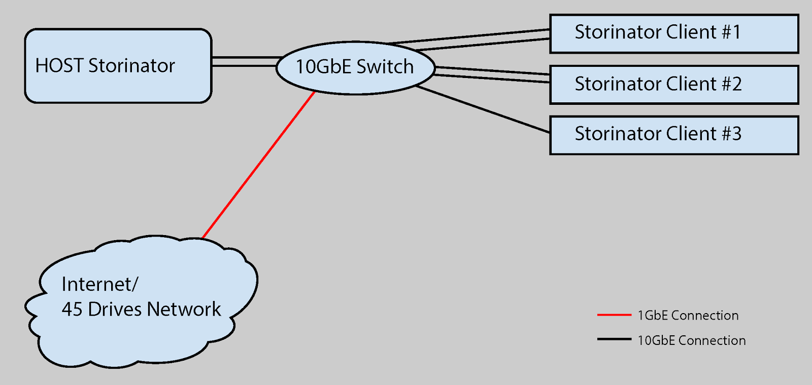
Now that my network is all strung together, and my server/clients can talk to each other through the 10GbE pipe, let’s move on to the fun part…testing the bandwidth of the new network!
TESTING THE BANDWIDTH
The way network bandwidth was first explained to me was that it was like a highway. The more lanes you have on a highway, the more traffic is able to travel at a high rate of speed. It works the same way with clients on a network transferring files to, and from, a storage server. The more bandwidth (lanes) you have, the more users you can have transferring files more quickly.
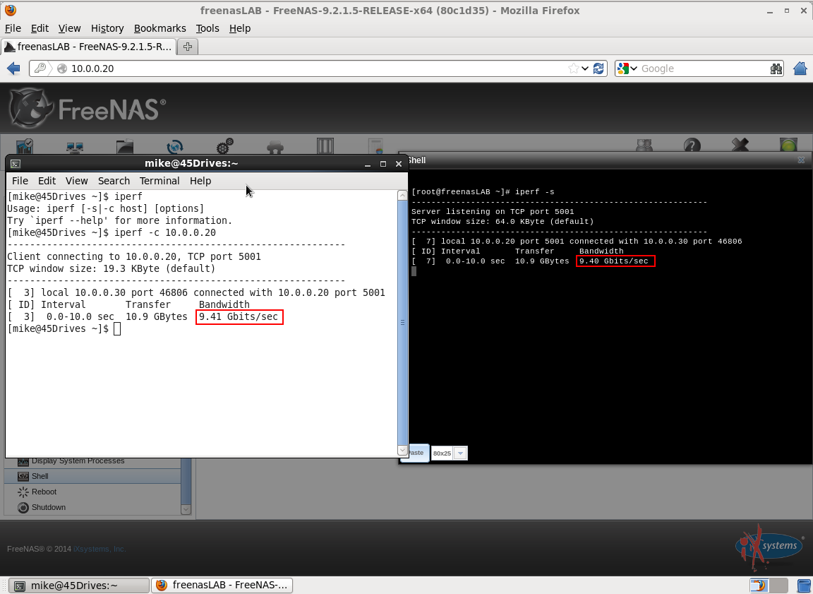
To test the bandwidth in all of my experiments, I used iperf, a well-known free network benchmark utility. Iperf quantifies the network bandwidth so we can verify that we have a 10 Gigabit connection between machines on our network. I like it because it works seamlessly in every OS.
EXPANDING ON 10 GIGABIT
A 10GbE network is fast, but our Storinator storage pods are faster. We have customers who are regularly exceeding read and write speeds beyond 2GBytes per second, and we achieve the same results in the lab. To move all of this data in and out of a pod requires connectivity that is two or three times what a single 10GbE connection offers.
So I wanted to push the limits of our 10GbE by experimenting with network bonding. There are other terms to describe this process, such as NIC teaming or link aggregation. To achieve network bonding, you set up multiple 10GbE connections from your machine to your switch, and tie them together. It can accomplish different results, including a bandwidth that is the sum of your connections.
Linux makes network bonding easy by offering a built-in module in the kernel, and the behavior of the bonded interface depends on which mode you choose. There are seven modes that come built in to the bonding module, each having their own unique feature. Generally speaking, modes provide either fault tolerance or load balancing services or a combination of the two. Each mode does have its drawbacks, so it is important to select the mode that best suits your application.
What sparked my interest was the fact that, theoretically, using the round-robin mode policy (mode 0 in Linux), we could double the network bandwidth between our machines with no additional hardware, just extra network cables.
HOW TO NETWORK BOND
Since the network bonding driver is pre-built into the Linux kernel, there is no need to install any extra packages. Conveniently, the switch does not need to be configured in any way for the round-robin policy.
In order to bond the network ports in CentOS, the first thing needed is to create a master bond config file in the network-scripts directory (e.g. /etc/sysconfig/network-scripts/ifcfg-bond0). This config file contains information like device name, IP address, subnet, bonding mode, etc. Most of this is entirely up to the user. It is important to note that I used mode 0 round-robin policy. Please see our technical wiki on implementing network bonding in CentOS for detailed information.
Next, we need to modify the existing individual network connections in order to make them part of a bonded interface. The un-bonded network interfaces are picked up on boot, so its just a matter of making a quick edit to each interfaces config file. Please see my technical wiki article showing you exactly what to put into your network config files.
FreeNAS is much more straightforward than CentOS. Upon boot, FreeNAS will give you a list of options from 1-14:
Aditionally, FreeNAS makes this process easier by adding a webGUI feature to allow you to bond interfaces. This is also documented on our wiki in the NAS Appliance Section.
Now that I have bonded my network interfaces using round-robin mode in hopes of doubling my bandwidth, let’s see if it worked!
RESULTS AND OPTIMIZATION
I tested the bandwidth achieved through network bonding in our lab, using the Host Storinator and Storinator Client #1, both running CentOS 7, each with a single Intel X540-T2 NIC Card to our Netgear XS708E switch.
I then ran iperf and saw our bandwidth was around 11.3 Gigabits/s.
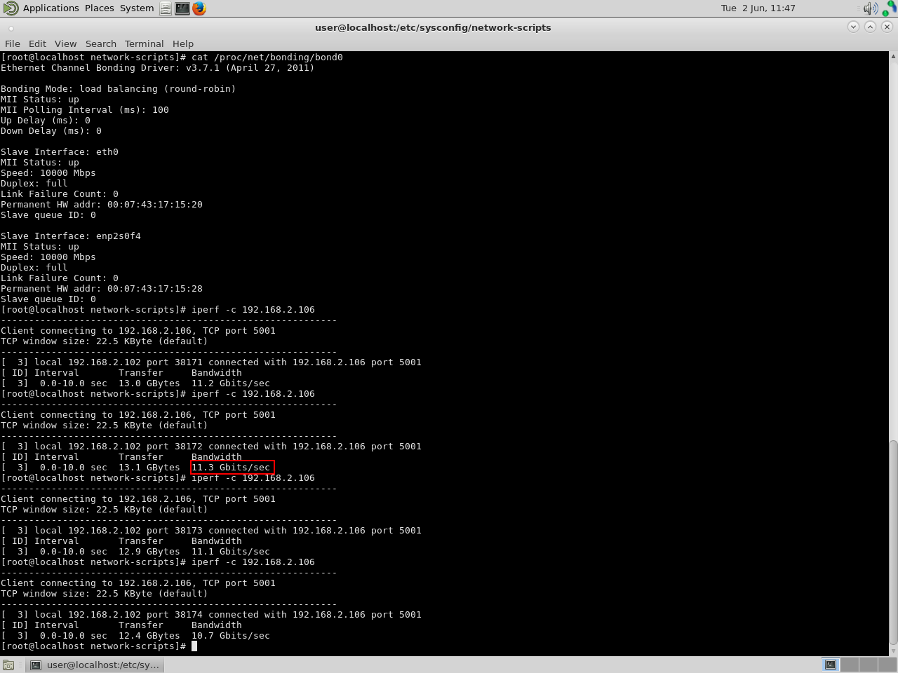
I was puzzled by this since I was expecting a number closer to 20 Gigabits/s, so I spent some time trying to tune our network. Some reading told me that the default TCP windows sizes resulted in poor performance when using the much newer 10GbE infrastructure so I then played with various TCP window sizes, but only saw further performance degradation.
Further investigation revealed the optimal TCP window size is directly related to the bandwidth-delay product, which is the product of the network speed (in bits per second) and its round-trip delay time (in seconds). When TCP was first defined (1974) the optimal window size was selected based on the current network speeds. Since then, however, we have dramatically increased our network speeds and so we therefore need to re-evaluate the optimal TCP window size. Luckily, it turns out that Linux (and most other OS) scales the TCP window size depending on your connection speed, therefore no tuning is required and the ideal window size will be determined by the kernel.
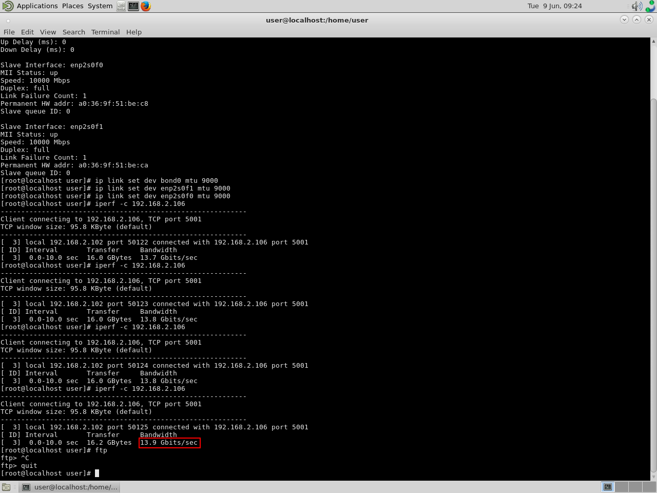
My next thought was to use jumbo frames rather than the default 1500bytes. Put another way, I considered how size of the packet of data that was being transmitted across the network. This is technically called MTU (Maximum Transmission Unit). Like the TCP window size, as network speeds increased as small MTU became less efficient.
Changing to jumbo frames did indeed make an improvement, increasing our bandwidth from 11.3 to 13.9Gbits. Because of that, I always keep the MTU at 9000 bytes on a 10GbE network. (A side note to keep in mind: when making this change yourself, make sure all of your components support jumbo frames. Most components made today have this support.)
Still stumped as to why I wasn’t seeing 20 Gigabits/s, I decided to place two Intel NIC Cards in each machine and bond 2 interfaces to the switch, one interface per card.
This resulted in success – I had a 20 Gigabit Connection!
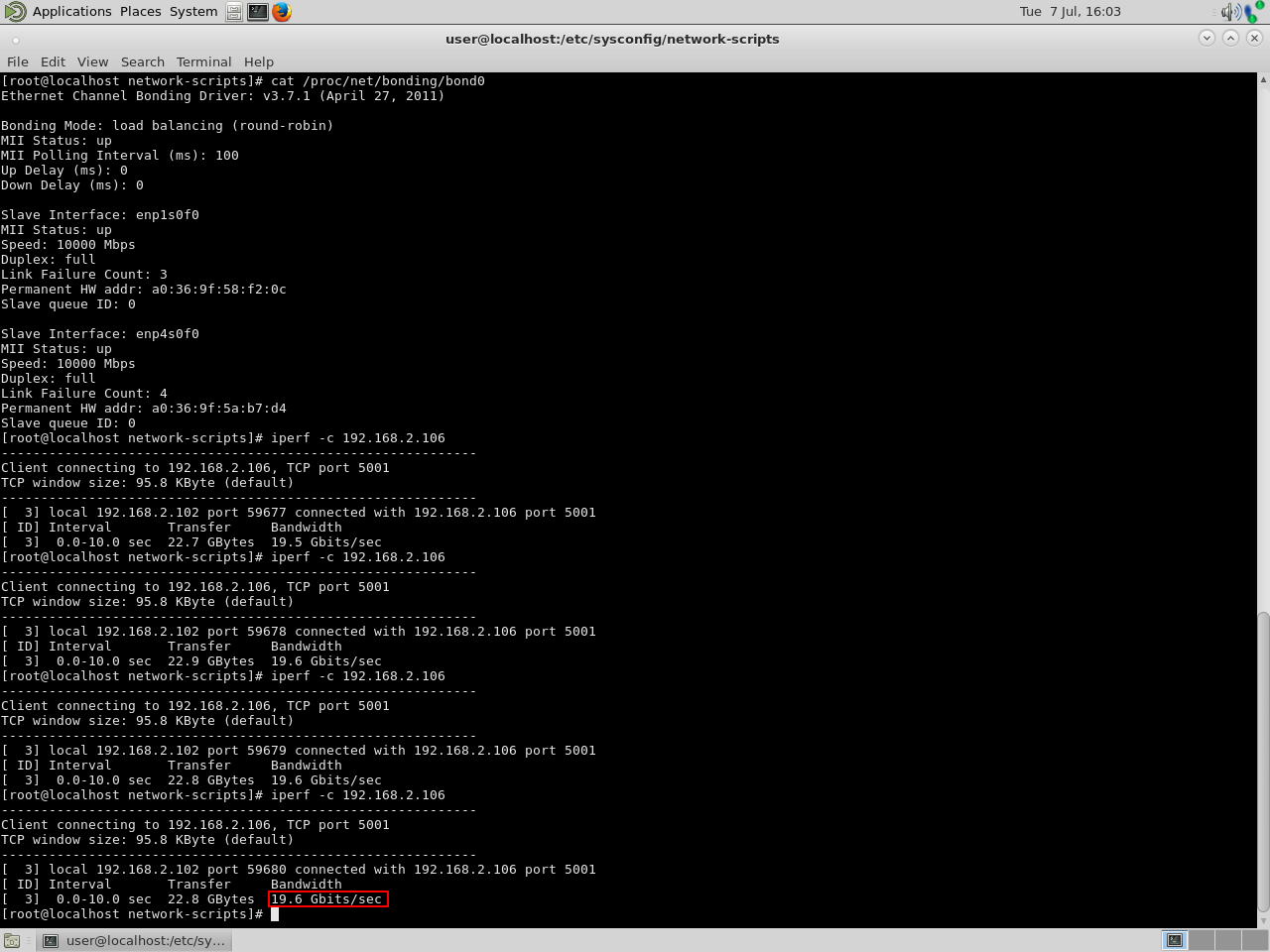
It turns out while the Intel cards are 10 Gigabit NICs, they cannot handle 10 Gigabit out of each port at once, only 14 Gigabit between the two (the bottleneck must be within the card architecture itself or the PCI connection).
Three NIC Cards with 3 interfaces will give you bandwidth just shy of 30 Gigabits/s. That is a very large highway!
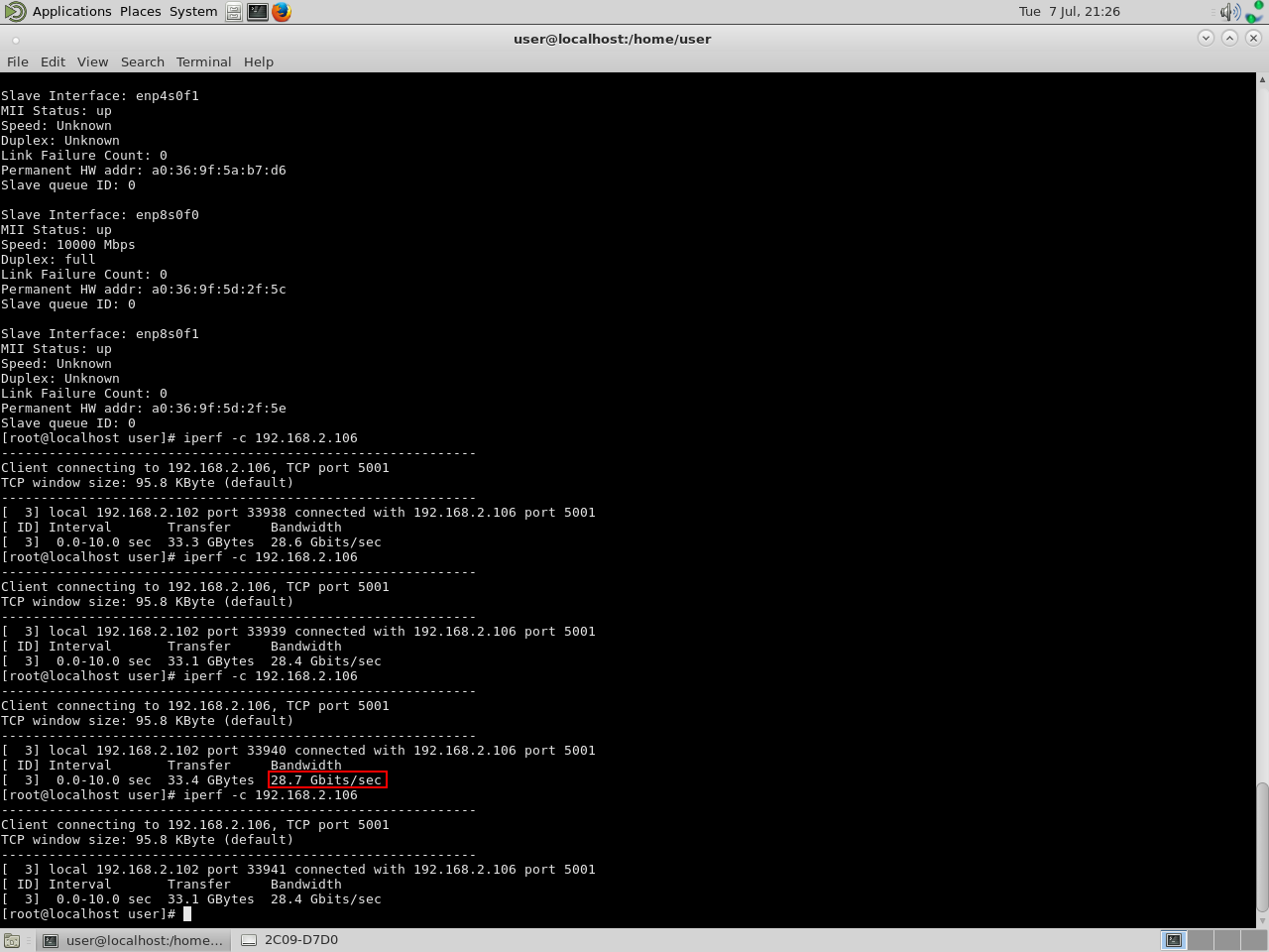
However, I believe that if you are trying to achieve bandwidth of 30Gb, you are better off using two NIC cards with two interfaces each, offering ~14Gb per card.
This way, you also achieve better redundancy, and your costs are lower compared to having three NIC cards.
CONCLUSION
While this post touched on how easy and inexpensive it is to set up a 10GbE network, my main focus was to share my experience with setting up a 20GbE network through network bonding.
In doing my experiments, I learned a few key things:
Newsletter Signup
Sign up to be the first to know about new blog posts and other technical resources